Table of Contents
1. Basic Definition & Core Advantages of PA66 Long Glass Fiber Composite
2. Standard Formula System of LGF PA66 Pellets 2.1 Base Resin & Long Glass Fiber Matching Ratio 2.2 Auxiliary Additives For Different Functional Grades 2.3 Color Masterbatch & Surface Compatibility Modifier
3. Key Physical Performance Indexes of Qualified LGF PA66 3.1 Mechanical Strength Index (Tensile, Flexural, Impact) 3.2 Thermal & Dimensional Stability Parameters 3.3 Anti-Creep, Anti-Warpage & Water Absorption Data
4. Standard Injection Molding Process Parameters For LGF PA66 4.1 Barrel Temperature & Drying Pre-Processing Requirement 4.2 Mold Temperature, Injection Speed & Holding Pressure Setting 4.3 Mold Structure Design Tips To Reduce Fiber Floating & Warpage
5. Lab Performance Comparison: LGF PA66 VS Short Glass Fiber PA66
6. Typical Mass Production Defects In LGF PA66 Molding & Solutions
7. Main Injection Molding Application Fields Of PA66 Long Glass Fiber
8. Industry FAQ About LGF PA66 Material Formulation & Molding Operation
1. Basic Definition & Core Advantages of PA66 Long Glass Fiber Composite
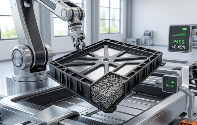
PA66 Long Glass Fiber, also shortened as LGF PA66 or LFT PA66, is long fiber reinforced thermoplastic composite produced via pultrusion impregnation process. Continuous long glass fibers are fully soaked by molten PA66 matrix, cut into uniform pellets with fiber length close to pellet length.
Compare with ordinary short glass fiber (SGF) PA66, long glass fiber inside LGF PA66 can maintain longer effective length after injection molding. It brings multiple core strengths for structural plastic parts: higher overall rigidity, outstanding creep resistance, lower shrinkage and better long-term dimensional stability under continuous load.
This composite material replaces die-cast aluminum, zinc alloy and thick solid plastic widely in automotive, new energy and heavy machinery industries. All formulation design, physical test standards and molding process parameters discussed in this guide follow ISO plastic material testing standards for industrial mass production.
2. Standard Formula System of LGF PA66 Pellets
: 2.1 Base Resin & Long Glass Fiber Matching Ratio
Pure PA66 resin serves as continuous matrix, and alkali-free long glass fiber acts as reinforcing filler. Common standard fiber content ratios in market are 20%, 30%, 40% and 50% by weight.
· LGF20 PA66: Low fiber loading, good toughness balance, for thin-wall small structural housings
· LGF30 PA66: Universal mainstream grade, balance of strength, cost and molding fluidity
· LGF40 / LGF50 PA66: Ultra-high stiffness, metal replacement heavy load structural brackets
Fiber length before pellet cutting keeps 10–12mm, which retains over 6mm effective fiber length after complete injection shear, far longer than 0.2–0.8mm residual fiber of SGF PA66.
: 2.2 Auxiliary Additives For Different Functional Grades
Functional additives are blended into formula according to service environment demands, total additive proportion controlled within 5% to avoid reducing base mechanical performance:
1. Heat stabilizer: Hindered amine composite stabilizer, improve long-term HDT and anti-oxidation under high temperature engine compartment
2. Hydrolysis resistant agent: Carbodiimide additive, suitable for new energy cooling liquid contact components
3. Low temperature toughener: POE elastomer, enhance notched impact strength for low-temperature outdoor parts
4. Lubricant: Internal/external composite lubricant, reduce fiber floating and mold wear during injection
: 2.3 Color Masterbatch & Surface Compatibility Modifier
Silane coupling agent is mandatory in all LGF PA66 formulas, to build tight bonding interface between glass fiber and PA66 resin, prevent fiber-resin separation under alternating load. Black, natural white and custom color masterbatch are added at the final pultrusion stage. High concentration masterbatch avoids uneven color streaks caused by uneven fiber dispersion.
3. Key Physical Performance Indexes of Qualified LGF PA66
All test data follows ISO 527, ISO 178, ISO 180, ISO 75 test standards, taking mainstream 30% LGF PA66 as reference sample:
: 3.1 Mechanical Strength Index (Tensile, Flexural, Impact)
· Tensile strength: 185–210 MPa
· Flexural strength: 270–300 MPa
· Flexural modulus: 11.5–13 GPa
· Notched Charpy impact strength: 18–24 kJ/m²
Higher fiber content (40%/50%) can lift tensile modulus above 16 GPa for heavy load bearing parts.
: 3.2 Thermal & Dimensional Stability Parameters
· Heat Deflection Temperature (HDT 1.82MPa): 245–260 ℃
· Molding shrinkage rate (flow direction): 0.3–0.5%; cross flow direction: 0.6–0.9%
· Continuous long-term service temperature: -40 ℃ ~ 140 ℃
Low shrinkage difference between flow and cross direction effectively controls part warpage after demolding and cooling.
: 3.3 Anti-Creep, Anti-Warpage & Water Absorption Data
· Creep deformation rate under 80MPa constant load (1000h): ≤0.45%
· Equilibrium water absorption (23℃ immersion): 1.6–2.1% Long glass fiber network restricts molecular chain movement of PA66 matrix, which cuts permanent creep deformation greatly compared with SGF PA66.
4. Standard Injection Molding Process Parameters For LGF PA66
: 4.1 Barrel Temperature & Drying Pre-Processing Requirement
PA66 absorbs moisture rapidly, fully drying is non-negotiable before molding:
· Drying condition: 80–85 ℃ hot air dryer, 4–6 hours, residual moisture ≤0.2%
· Barrel temperature setting: Feed zone 260℃, middle melting zone 270–280℃, nozzle 275–285℃ Too high barrel temperature will cause PA66 thermal degradation and fiber interface bonding failure.
: 4.2 Mold Temperature, Injection Speed & Holding Pressure Setting
· Mold temperature: 85–110 ℃; high mold temp improves fiber uniform distribution and surface gloss
· Injection speed: Medium-high speed for thin wall; medium low speed for thick structural brackets to reduce fiber floating
· Holding pressure: 70–100 MPa, longer holding time to stabilize dimensional shrinkage
: 4.3 Mold Structure Design Tips To Reduce Fiber Floating & Warpage
1. Gate design: Large rectangular side gate or submarine gate, avoid thin pinpoint gate that generates severe fiber shear
2. Uniform wall thickness: Wall thickness difference controlled within 1.2mm to prevent uneven shrinkage warpage
3. Even cooling circuit layout: Symmetric cooling channels balance mold surface temperature difference
4. Rib structure: Thickened rib root to eliminate stress concentration and surface sink mark
5. Lab Performance Comparison: LGF PA66 VS Short Glass Fiber PA66
Test sample: 30% fiber content for both materials, test under unified ISO standard
表格
Test Index | 30% LGF PA66 (Long Glass Fiber) | 30% SGF PA66 (Short Glass Fiber) | Practical Molding & Service Impact |
Residual fiber length after injection | 5–7 mm | 0.3–0.7 mm | Longer fiber forms continuous bearing network |
Tensile modulus | 12.2 GPa | 8.1 GPa | LGF part rigidity improves over 50% |
1000h creep deformation rate | 0.42% | 1.38% | SGF parts deform permanently under long load |
Molding shrinkage difference (flow / cross) | 0.35% | 1.12% | SGF parts serious warpage after cooling |
Notched impact strength | 21.5 kJ/m² | 12.3 kJ/m² | LGF parts resist sudden impact fracture |
Long-term high temp aging retention rate | 87% | 62% | LGF maintains strength in engine compartments |
6. Typical Mass Production Defects In LGF PA66 Molding & Solutions
1. Surface fiber floating, matte rough texture: Low mold temperature, too fast injection speed; increase mold temp, reduce filling speed
2. Severe part warpage: Uneven wall thickness, asymmetric cooling; optimize rib layout and cooling channel design
3. Brittle easy fracture at rib root: Insufficient drying, over high barrel temperature; extend drying time, lower melting zone temp
4. Large dimensional fluctuation batch to batch: Unstable holding pressure, uneven moisture; fix holding parameter, standardize drying procedure
5. Visible silver streaks on surface: Residual moisture inside pellets; extend hot air drying cycle
7. Main Injection Molding Application Fields Of PA66 Long Glass Fiber
1. Automotive structural components: Engine brackets, cooling system housing, suspension plastic supports, throttle valve structural parts
2. New energy industry: High-voltage connector shells, battery module fixing frames, motor end caps, charging gun structural inserts
3. Heavy industrial machinery: Gear housing, pump valve body, transmission plastic sliding blocks, metal replacement bearing brackets
4. Electronic & electrical appliances: Large-size power distribution box frame, thick-wall insulating structural bases
5. Outdoor durable equipment: Agricultural machinery plastic parts, construction equipment lightweight structural brackets
8. Industry FAQ About LGF PA66 Material Formulation & Molding Operation
Q1: What fiber content LGF PA66 is most widely used for general structural injection parts?
A1: 30% long glass fiber PA66 is the universal grade. It balances mechanical performance, material fluidity and raw material cost, suitable for most automotive and new energy structural brackets.
Q2: Why LGF PA66 has much lower creep deformation than short glass fiber PA66?
A2: Long glass fibers keep continuous interlaced network inside molded parts after injection, which restricts PA66 molecular chain creep movement under long constant load. Short broken fibers cannot form stable supporting structure.
Q3: Can LGF PA66 replace aluminum alloy die casting for heavy load structural brackets?
A3: 40% / 50% high fiber content LGF PA66 with heat stabilized formula can replace thin-wall aluminum alloy brackets under medium load, realize lightweight and reduce production machining cost.
Q4: What drying standard must be followed before LGF PA66 injection molding?
A4: Dry pellets at 80–85 ℃ for minimum 4 hours, test residual moisture below 0.2%. Undried material causes silver marks, brittleness and unstable mechanical performance on finished parts.