
1. Introduction: Why Fiber Length Is the Variable That Changes Everything
I have been working in composite materials sourcing for over a decade, and I can tell you that the single most consequential decision in specifying a fiber-reinforced thermoplastic is not the fiber type. It is not the resin. It is the fiber length.
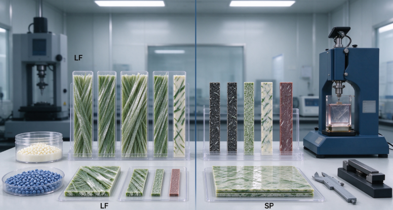
The difference between a long fiber thermoplastic composite (LFT) and a short fiber thermoplastic composite (SFT) looks almost trivial on a data sheet. LFT pellets carry fibers in the 6 to 25 mm range. SFT pellets carry fibers in the 0.2 to 1.0 mm range. Both use the same polymer matrices — PP, PA6, PA66, PBT, PPS — and both use the same reinforcement fibers — glass, carbon, aramid. Yet the mechanical performance gap between them can exceed 100% in impact strength and dramatically alter fatigue behavior over millions of cycles.
This is not a marginal improvement. It is a fundamental difference in how the composite handles stress, distributes load, and resists failure. For B2B buyers specifying materials for structural components — automotive underbody parts, industrial equipment housings, consumer electronics chassis — understanding this difference is the difference between a component that lasts and one that fails prematurely.
The global long fiber thermoplastics market was valued at USD 4.10 billion in 2025 and is projected to grow to USD 7.83 billion by 2032, with a CAGR of 9.66%. This growth is driven by the automotive industry's demand for lightweight structural components, the expansion of electrification requiring robust battery housings, and the adoption of LFT in construction and consumer electronics.
This guide breaks down the mechanical performance data, the fatigue behavior, and the impact energy absorption characteristics that distinguish LFT from SFT. I will cover the anisotropy trade-off that specifiers consistently underestimate, the manufacturing methods that determine retained fiber length, and a real-world case study from the automotive sector that demonstrates what these materials can achieve.
2. What LFT and SFT Actually Are
Let me start with the definitions, because there is some confusion in the market about where the boundary lies.
Short Fiber Thermoplastics (SFT) are composites in which the reinforcing fibers typically range from 0.2 mm to 1.0 mm in length. These fibers are compounded into the polymer matrix using twin-screw extrusion, a process that produces excellent fiber dispersion but causes significant fiber breakage. The fibers that end up in the finished part are often shorter than the fibers that went into the extruder.
Long Fiber Thermoplastics (LFT) , sometimes called LFRT (Long Fiber Reinforced Thermoplastics), contain fibers ranging from 6 mm to 25 mm in length. These fibers are produced through a pultrusion process in which continuous fiber rovings are pulled through a molten polymer bath, impregnated, cooled, and then cut into pellets of the desired length. The fibers in LFT pellets retain their length and are aligned along the pellet axis, typically at 12 mm.
The critical distinction is not just the initial fiber length but the retained fiber length in the finished part. LFT pellets are designed so that the fiber length is preserved during processing, while SFT compounding inherently shortens fibers through mechanical attrition. This is why LFT composites exhibit fiber aspect ratios (length-to-diameter ratio) that are an order of magnitude greater than those of SFTs, often exceeding L/D of 2000. This high aspect ratio is what allows LFTs to take full advantage of the reinforcing fiber's intrinsic strength.
The resin systems used for LFT are predominantly polypropylene (PP), followed by polyamide (PA6 and PA66), with PBT, PPS, and SAN used for specialty applications. JRBESTE, a manufacturer specializing in LFRT materials, produces long glass fiber reinforced pellets in PA66, PA6, PP, ABS, PEEK, TPU, PBT, and PPS, reflecting the broad range of matrix options available in the market.
3. Mechanical Performance: The Data Behind the Difference
The mechanical performance comparison between LFT and SFT is where the fiber length difference translates directly into measurable property improvements.
A comparison of 30% long glass fiber reinforced PP (LFT-PP30%) versus 30% short glass fiber reinforced PP (SFT-PP30%) shows that LFT-PP outperforms SFT-PP across every key mechanical metric: tensile strength, flexural strength, flexural modulus, impact strength, heat deflection temperature, and shrinkage. These are not marginal improvements. The impact strength of LFT-PP with 30-40% glass fiber content ranges from 25 to 30 kJ/m², which is significantly higher than comparable SFT formulations.
The mechanism behind this improvement is straightforward. In a composite material, stress applied to the matrix is transferred to the reinforcing fibers through shear at the fiber-matrix interface. The efficiency of this stress transfer depends on the fiber length relative to the critical fiber length — the minimum length required for the fiber to carry its full fracture strength. Fibers shorter than the critical length cannot be loaded to their full capacity; they slip within the matrix rather than breaking. Fibers longer than the critical length can be loaded to their full tensile strength.
In LFT composites, the fiber length in the finished part is typically well above the critical length, meaning the fibers are being used at or near their full reinforcing potential. In SFT composites, the fiber length often falls below the critical length, meaning a significant portion of the reinforcement capacity is wasted. Research has shown that tensile strength increases with fiber length, with significant gains observed as fiber length increases from 10 mm to 25 mm in various composite systems.
The flexural modulus and tensile modulus of LFT composites are also consistently higher than SFT alternatives. This translates directly to improved dimensional stability and load-bearing capacity in structural applications. For automotive components such as front-end carriers and seat back frames, this stiffness improvement allows designers to replace metal parts with LFT composites while maintaining structural performance.
4. Fatigue Life: How Fiber Length Determines Cyclic Durability
Fatigue is the failure mode that kills components slowly. It occurs when a material is subjected to repeated cyclic loading — the kind of loading that automotive suspension components, seat frames, and powertrain mounts experience every time a vehicle moves. Understanding how LFT and SFT composites respond to cyclic loading is essential for any application where the component will see millions of stress cycles over its lifetime.
The fatigue behavior of LFT composites has been extensively studied, particularly for glass fiber reinforced polypropylene systems. Research on PP/20 vol.% E-glass fiber LFT composites has shown that samples tested along the longitudinal direction exhibit higher fatigue life than transverse samples, a result of the preferential fiber orientation developed during processing. The S-N curves for these materials follow a power law relationship, allowing fatigue life prediction based on stress amplitude.
But the most important finding for LFT versus SFT comparison comes from research on fiber length effects. Long glass fiber thermoplastics have been shown to exhibit higher fatigue crack propagation resistance than short glass fiber composites. The reason is the number of stress concentration sites. In SFT composites, every fiber end is a potential stress concentration point — a location where the local stress exceeds the average stress and where cracks can initiate. Because SFTs have many more fiber ends per unit volume than LFTs (due to their shorter length), they have more potential crack initiation sites.
This is not a theoretical advantage. It is a measurable difference in fatigue life that becomes more pronounced as the number of cycles increases. For a component that must survive 10⁶ cycles or more, the fiber-end effect can mean the difference between passing and failing a durability specification.
Research on direct/inline compounded (DLFT) composites — a variant where long fibers are created directly during extrusion — has produced fatigue life prediction curves for 40% carbon fiber/PA66 composites. At 0° orientation with respect to flow, the peak stress at 10⁶ cycles was 105 MPa. At 45° orientation, it dropped to 72 MPa. At 90° orientation, it fell to 53 MPa. These numbers demonstrate both the potential and the anisotropy of LFT fatigue performance.
There is one nuance worth noting. A comparison of normalized S-N data for thermoplastic composites suggests that long fiber composites tend to deteriorate by fatigue slightly faster than short fiber composites in the high-cycle range. This means that while LFT has superior static strength and fatigue crack propagation resistance, the rate of fatigue degradation in the very high cycle regime may be comparable or slightly worse than SFT. For most structural applications where fatigue life is determined by crack initiation rather than propagation, the LFT advantage in crack initiation resistance dominates. But for applications where existing flaws are present, this nuance should be considered.
5. Impact Energy Absorption: Why LFT Absorbs More Energy Per Unit Mass
Impact energy absorption is the property that most clearly separates LFT from SFT, and it is the property that makes LFT composites attractive for crash-resistant structural components.
The data is unambiguous. PP + LGF30/40 impact strength ranges from 25 to 30 kJ/m², significantly outperforming other reinforced materials at comparable fiber loading levels. The impact strength of LFT is roughly double that of comparable SFT formulations. For a safety-critical component — a seat back frame, a bumper beam, a battery enclosure — doubling the impact strength translates directly to improved occupant protection and crashworthiness.
The mechanism behind this improvement is the energy dissipation during fiber pull-out. When a composite is subjected to impact loading, energy is absorbed through multiple mechanisms: fiber fracture, matrix cracking, fiber-matrix debonding, and fiber pull-out. In SFT composites, the short fibers are pulled out of the matrix relatively easily because there is less fiber surface area for shear transfer. In LFT composites, the longer fibers require significantly more energy to pull out because the shear transfer zone along the fiber length is much greater. This fiber pull-out mechanism is the primary reason for the superior impact energy absorption of LFTs.
Research on LFT energy absorption has led to the development of the power law equation relating absorbed energy to impact energy, normalized by penetration energy. This allows designers to calculate the minimum penetration energy of an LFT plate based on material parameters and test constraints, enabling initial material selection based on impact resistance requirements. The rear bumper beam structure of vehicles, for example, can be designed with LFT materials to satisfy crash performance requirements through controlled compression and collapse that absorbs collision energy.
JRBESTE's long fiber reinforced thermoplastic materials are specifically positioned for applications where impact strength is critical, including automotive engine components, structural parts, and rail transportation components requiring fire retardancy and durability.
6. Anisotropy: The Trade-Off Nobody Talks About
I have focused on the advantages of LFT so far, but there is a significant trade-off that every specifier needs to understand. LFT composites are highly anisotropic — their properties vary dramatically depending on the direction of loading relative to the fiber orientation.
The fatigue data I cited earlier illustrates this clearly. For DLFT carbon fiber/PA66, the peak stress at 10⁶ cycles was 105 MPa in the flow direction but only 53 MPa at 90° to flow. That is a 50% reduction in fatigue strength simply from changing the loading direction. The same anisotropy applies to tensile strength, flexural modulus, and impact resistance.
SFT composites, by contrast, exhibit more isotropic behavior because their shorter fibers are more randomly oriented and more uniformly distributed. For components with complex loading conditions — where stress comes from multiple directions — SFT may provide more predictable performance.
This is not a reason to avoid LFT. It is a reason to design carefully. LFT components should be designed so that the primary load path aligns with the fiber flow direction. For components where this is not possible, hybrid designs using LFT in unidirectional load paths and SFT or unreinforced polymer in multi-directional load paths may be the better solution.
The practical implication for B2B buyers is straightforward: when you receive LFT material data, check the test direction. A tensile strength value without a direction specification is incomplete. Request data for 0°, 45°, and 90° orientations where possible, and design your component to take advantage of the fiber orientation.
7. Head-to-Head: Complete Comparison Table
The following table summarizes the key performance and processing differences between LFT and SFT composites.
Parameter | LFT (Long Fiber Thermoplastic) | SFT (Short Fiber Thermoplastic) |
Fiber length in pellets | 6–25 mm (typically 12 mm) | 0.2–1.0 mm |
Retained fiber length in part | 3–15 mm (depends on process) | 0.2–0.5 mm |
Fiber aspect ratio (L/D) | >2000 | <100 |
Tensile strength | Higher — fibers carry full load | Lower — many fibers below critical length |
Flexural modulus | Higher | Lower |
Impact strength | 25–30 kJ/m² (PP+30-40% LGF) | ~12–15 kJ/m² (PP+30-40% SGF) |
Fatigue crack propagation resistance | Higher — fewer fiber ends as stress concentrators | Lower — more fiber ends |
Fatigue life (high-cycle) | Superior in crack initiation; may degrade slightly faster | Superior in crack propagation once initiated |
Anisotropy | High — properties vary significantly with direction | Low — more isotropic behavior |
Creep resistance | Superior — PP+LGF40 outperforms SFT-PP+GF40 and PA66+GF30 | Inferior |
Thermal expansion coefficient | Closer to metals; PP-LGF40 approaches metal-like CTE | Higher, more temperature-sensitive |
Heat deflection temperature | Higher | Lower |
Shrinkage | Lower | Higher |
Density (typical) | 1.12–1.25 g/cm³ (PP-based) | 1.12–1.25 g/cm³ (PP-based) |
Recyclability | Mechanical recycling possible; fiber length degrades | Mechanical recycling possible |
Relative cost | Higher | Lower |
Sources: China Textile News (LFT vs. SFT data), ScienceDirect fatigue studies, industry data
8. Manufacturing Methods and Their Effect on Fiber Length
The performance advantage of LFT depends entirely on preserving fiber length through the manufacturing process. This is where the choice of manufacturing method becomes critical.
Pultrusion is the dominant method for producing LFT pellets. Continuous fiber rovings are pulled through a molten polymer impregnation die, where the thermoplastic fully wets and encapsulates the fibers. The impregnated strand is then cooled and cut into pellets of the desired length — typically 12 mm. This process produces excellent fiber impregnation and preserves fiber length almost completely.
JRBESTE's LFT production process follows a similar sequence: material selection, R&D testing, fiber compounding, extrusion and pelletizing, quality inspection, and packaging. The company operates a 38-acre facility with 20,000 tons per year of production capacity and holds ISO/TS 16949 certification for automotive quality management.
Injection molding is the most common process for converting LFT pellets into finished parts. However, injection molding causes fiber breakage due to the high shear forces in the screw and nozzle. Retained fiber length in injection-molded LFT parts is typically 3 to 8 mm — still well above the critical length for most glass fiber systems, but shorter than the original 12 mm pellet length.
Compression molding produces even better fiber length retention because the material flows less during processing. DLFT (Direct Long Fiber Thermoplastic) processes, where fibers are compounded directly into the molding press, can achieve retained fiber lengths of 10 to 25 mm. Research on DLFT carbon fiber/PA66 composites has demonstrated the fatigue performance achievable with these longer retained fiber lengths.
For SFT composites, twin-screw extrusion compounding is the standard method. The high shear in the twin-screw extruder disperses the fibers uniformly but breaks them down to lengths of 0.2 to 0.5 mm. This is why SFT composites have lower mechanical performance — the fibers are simply too short to carry their full load.
The practical implication for sourcing is that the manufacturing method must be matched to the performance requirement. If you need maximum impact strength and fatigue life, specify compression-molded LFT or DLFT with retained fiber length above 10 mm. If you need good flow characteristics for complex geometries, injection-molded LFT with retained fiber length of 3 to 8 mm may be the better choice. If you need isotropic properties and low cost, SFT may be sufficient.
9. Case Study: LFT Seat Back Frames in Passenger Vehicles
The most instructive case study for LFT performance in a real-world application comes from the automotive industry, where weight reduction and crash safety are simultaneously critical requirements.
The original design for a passenger car rear seat back frame used a steel structure. The steel frame met all safety requirements but added significant weight to the vehicle — weight that directly increased fuel consumption and reduced the efficiency of the vehicle's powertrain.
The redesign replaced the steel frame with a long glass fiber reinforced thermoplastic (LFT) structure. The design process integrated topology optimization with energy absorption modeling to determine the force transmission paths and detailed structure design under both forward and rearward loading conditions.
The results were significant. The LFT seat back frame achieved the required crash performance while reducing weight. The energy absorption modeling confirmed that the LFT structure could absorb the required impact energy through controlled compression and collapse. The topology optimization ensured that material was placed only where it was needed for load-bearing, minimizing weight without compromising safety.
This application demonstrates the core value proposition of LFT composites: the ability to replace metal structures with lighter polymer composites while maintaining or improving crash performance. The key enabler is the impact energy absorption capacity of long fibers — a capacity that short fiber composites cannot match.
For B2B buyers in the automotive supply chain, this case study illustrates the specification approach: define the crash energy absorption requirement, model the component with LFT material properties, optimize the topology for the load path, and validate with physical testing. The material data must include impact strength and energy absorption characteristics at the relevant strain rates, not just static tensile properties.
10. Practical Sourcing Framework for B2B Buyers
If you are sourcing fiber-reinforced thermoplastic composites for structural applications, here is the framework I recommend.
Step 1: Define the dominant loading mode. Is the component primarily loaded in tension, compression, impact, or fatigue? For impact-dominated applications, LFT is the clear choice. For fatigue-dominated applications, LFT offers superior crack initiation resistance but requires careful design to account for anisotropy.
Step 2: Determine the required fiber length retention. Specify the retained fiber length in the finished part, not just the pellet length. For injection-molded LFT, specify a minimum retained length of 3 mm. For compression-molded LFT or DLFT, specify a minimum of 10 mm. Request fiber length distribution data from your supplier.
Step 3: Specify the loading direction and request directional data. LFT properties are highly anisotropic. Request tensile, flexural, and impact data for 0° and 90° orientations. Design your component to align the primary load path with the fiber flow direction.
Step 4: Evaluate the manufacturing method for your geometry. Injection molding is suitable for complex geometries but causes fiber breakage. Compression molding and DLFT preserve fiber length but require simpler part geometries. Match the process to the part.
Step 5: Request fatigue data if the application is cyclic. For components subjected to repeated loading, request S-N curve data. JRBESTE and other LFT suppliers can provide fatigue characterization data for their materials. The data should specify the stress ratio (R-value), test frequency, and fiber orientation.
Step 6: Verify certification and quality systems. For automotive applications, ISO/TS 16949 is the minimum quality management requirement. JRBESTE holds this certification, along with 40+ patents in LFRT and CFRTP technologies.
Sourcing Parameter | Recommended Specification | Verification Method |
Fiber length (pellet) | ≥12 mm for injection molding; ≥20 mm for compression molding | Supplier specification |
Retained fiber length (part) | ≥3 mm injection molded; ≥10 mm compression molded | Fiber length distribution test |
Fiber content | 30–50% by weight (glass); 20–40% (carbon) | TGA or burn-off test |
Impact strength | ≥25 kJ/m² (PP+30-40% LGF) | Charpy or Izod per ISO 179 |
Tensile strength (0°) | ≥100 MPa (PA66+30% LGF) | ISO 527 |
Fatigue strength at 10⁶ cycles | ≥50 MPa (PA66+30% LGF, R=0.1) | S-N curve per ISO 13003 |
Anisotropy ratio (0°/90°) | ≤2.5:1 for structural parts | Directional tensile testing |
Quality system | ISO/TS 16949 for automotive | Certificate verification |
11. Frequently Asked Questions
Q: What is the main difference between LFT and SFT composites?
LFT composites contain fibers 6 to 25 mm long, while SFT composites contain fibers 0.2 to 1.0 mm long. The longer fibers in LFT provide superior tensile strength, impact resistance, fatigue life, and creep resistance because they can be loaded to their full reinforcing potential rather than slipping within the matrix.
Q: How much stronger is LFT compared to SFT?
The impact strength of LFT is roughly double that of comparable SFT formulations. Tensile and flexural strength are also significantly higher — typically 30% to 50% depending on the fiber content and resin system. The exact improvement depends on the specific fiber and matrix combination, but the qualitative advantage is consistent across all material systems.
Q: Is LFT better than SFT for fatigue applications?
For fatigue crack initiation — the phase before a crack has formed — LFT is superior because it has fewer fiber ends that act as stress concentrators. For fatigue crack propagation — the phase after a crack has formed — the comparison is more nuanced, with some research suggesting SFT may perform comparably or slightly better in the high-cycle regime. For most structural applications, the crack initiation advantage of LFT dominates.
Q: Can LFT be recycled?
Yes. LFT composites can be mechanically recycled, although the fiber length degrades during the recycling process, reducing mechanical properties. The recyclability of LFT is one of its advantages over thermoset composites, which cannot be easily recycled.
Q: What is the cost difference between LFT and SFT?
LFT materials cost more per kilogram than SFT materials because of the additional processing required to produce long fiber pellets through pultrusion. However, the performance advantage often allows for thinner wall sections or reduced part weight, which can offset the material cost premium. The total cost of ownership depends on the specific application.
Q: What fiber types are available for LFT composites?
Glass fiber is the most common reinforcement for LFT composites, followed by carbon fiber for higher-performance applications. Aramid fiber is used for specialty applications requiring high impact resistance and low density. JRBESTE produces LFT pellets with glass fiber and carbon fiber reinforcement across multiple polymer matrices including PA66, PA6, PP, PBT, PPS, and PEEK.
12. Final Thoughts
Let me leave you with this.
The choice between long fiber and short fiber thermoplastic composites is not about which material is better in absolute terms. It is about matching the material to the application. LFT composites offer superior mechanical performance, fatigue life, and impact energy absorption — but they cost more, they are more anisotropic, and they require more careful design to account for fiber orientation effects.
The data is clear. LFT impact strength is double that of SFT. LFT fatigue crack propagation resistance is higher because of fewer stress concentration sites. LFT creep resistance outperforms even PA66+GF30. And LFT thermal expansion is close to that of metals, making it a viable replacement for steel and aluminum in structural components.
The market is responding. The LFT market is growing at nearly 10% annually, driven by automotive lightweighting, electrification, and the need for recyclable structural materials. JRBESTE and other LFT manufacturers are expanding production capacity to meet this demand.
If you are specifying fiber-reinforced composites for a structural application, my advice is straightforward. Start by defining the dominant loading mode — impact, fatigue, creep, or static load. If impact and fatigue dominate, LFT is the right family. If the loading is complex and multi-directional, consider a hybrid design or accept the trade-off of SFT's lower but more isotropic performance.